Blog-post
Construction joints: settle them in the drawings, not on the slab

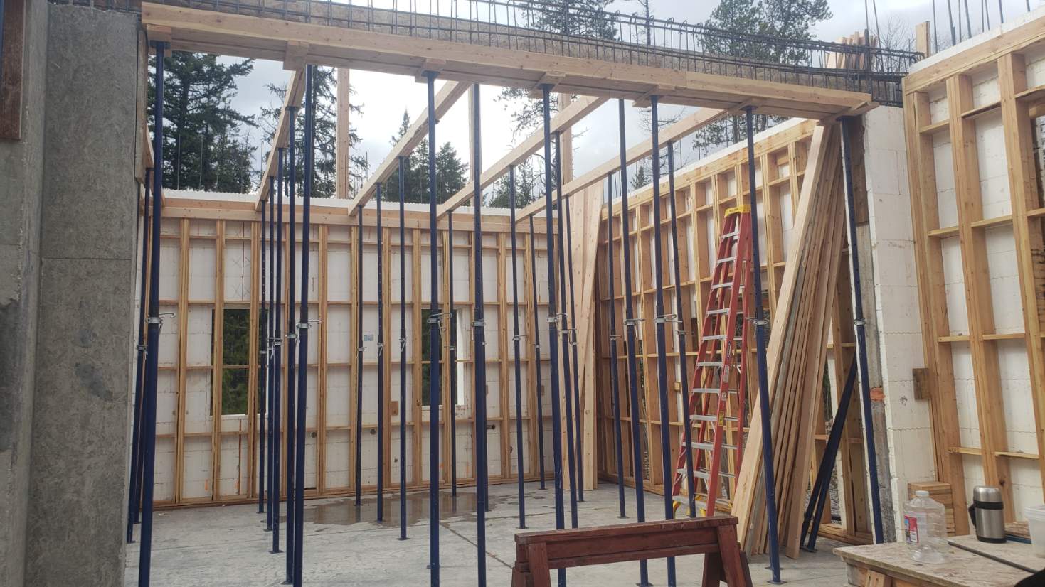
Your next pour is booked for Thursday, and the superintendent is looking at the wall elevation again. The joint line on the structural sheet sits at grid line C, but the formwork detail puts the stop two bays over. Somebody now has to decide where the concrete stops, and the trucks are already on the road.
The fix is to draw every construction joint on the formwork layout and the pour map before the concrete arrives, so the crew builds from one set of lines.
Why a joint is a formwork decision too
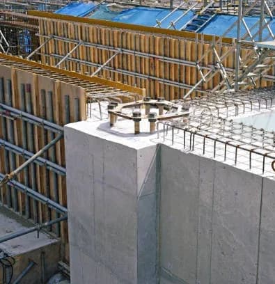
A construction joint is a formwork decision as well as a structural one. A construction joint is a planned stop in a concrete pour, where fresh concrete will later meet concrete that has already hardened. The structural drawings show where the joint is needed for the structure. The formwork has to close that joint, carry the panels on each side, and be stripped and moved without disturbing the placed concrete.
Move a joint and the panel count changes, the rebar laps change and the pour sizes change. That change belongs on the drawings, not in a decision made with a tape measure on the day.
A joint the formwork cannot close cleanly will be argued about on the day of the pour.
How joint positions set the pour sequence
Take a typical 300 mm (about 12 in.) thick core wall, 3.6 m (12 ft) high and 24 m (79 ft) long, as an example. The joint positions decide the size of each pour, so work through them in this order:
- Mark each joint line on the structural plan and the wall elevation, dimensioned from a grid line.
- Split the wall into pour lengths that the concrete supplier and the pump can place in one continuous operation.
- Number the pours in the order they will be placed, and use the same numbers on the pour map.
- Count the wall panels for each pour from the formwork model, and tie the rental days to the pour dates.
- Show the stripping order on the layout.
Reading the wall this way shows the foreman where the first pour ends before the crew sets a single panel.

What belongs on the drawings the crew builds from
A joint is only useful if the crew can find it on the paper in their hand. Check that each formwork set shows:
- The joint line, dimensioned from the grid, on the formwork layout
- The pour number on the pour map, matching the placing sequence
- The stop-end form and the panel that closes it at each joint
- The tie positions nearest each joint, marked on the wall elevation
- The panel quantities for each pour, taken from the same model
On site, the foreman walks the stop-end before the first truck arrives. The form should sit on the joint line, fit tight against the wall face so paste does not leak out, and have its slots cut where bars pass through. If any of that is missing from the drawing, the crew is left guessing.

We model the formwork in 3D and clash-check it against the rebar, so a stop-end form that would land on a placed bar shows up before the panels are cut. The quantities are counted panel by panel from that same model, which keeps the pour map and the bill of quantities telling the same story.
The one thing to do before the next pour
Before your next pour, take the structural sheets and mark every construction joint against the grid lines, then check that each joint has a pour number. Send those sheets, your formwork list and the pour dates for a fixed-price formwork quote.
Request a formwork quotation: https://formworkforconcrete.com/contact-us/
#Formwork, #FormworkDesign, #ConstructionJoints, #PourSequence, #ShopDrawings, #ConcreteConstruction