Projects
F.M. Woods WTP Upgrades
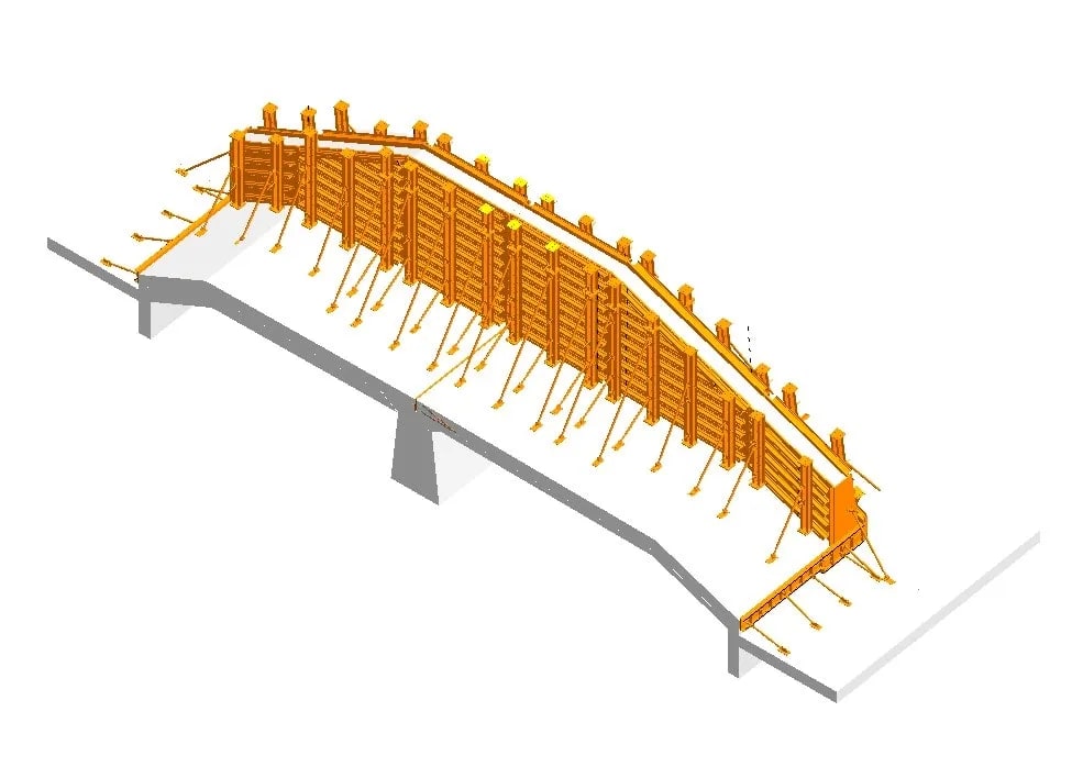
Wall formwork for a water treatment plant upgrade, drawn pour phase by pour phase for Sercon Construction.
Timber panels, walers, ties and waterstops, with a panel schedule for every phase.

Phased wall formwork for a water treatment plant
For the F.M. Woods water treatment plant upgrade in the United States, Sercon Construction asked us for formwork drawings for the new concrete walls and box structures. The engineer had already set the pour breaks. Our job was to turn each pour into forms the crew could build in the yard, set, pour and strip.

Questions before drawings
Before sizing a single panel, we went through the engineer's pour break drawing and sent our questions back in a phasing and clarification document: which elements are solid, when the concrete fill is placed, and where the construction joints fall.
Two walls carried a crane corbel, and the pour break drawing divided them differently in two sections. We were concerned that concrete placed in the higher wall panels would flow down into the lower ones, so we proposed splitting those walls at the corbel and aligning the other pour break with it, and asked for confirmation before the formwork was dimensioned.
What we delivered
- Formwork drawings for every pour phase, each sheet with a plan, sections, details and a 3D view
- A panel schedule per phase: every wall panel with its size, count, lumber length and plywood area
- Waler and lumber schedules, so the timber could be ordered and cut in advance
- The Revit formwork model behind the drawings
- Revisions after Sercon's mark-ups, issued phase by phase as the work started


Formwork system
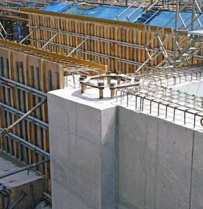
Site-built timber: plywood panels framed in lumber, the largest 8 ft × 21 ft, with 4×4 walers, form ties and corner ties. Filler pieces close the gaps where new walls meet the existing structure, waterstops are shown at the construction joints, and pile supports are drawn where walls sit over piles.
How this kind of form carries the concrete pressure, and how ties and walers are spaced, is explained in Timber Wall Formwork: Ties, Walers and Bracing.
EXPERTISE
We specialize in design and formwork modeling services, utilizing BIM technology to provide precise material estimates and scheduling.
We have successfully completed numerous challenging and complex projects, ensuring optimal efficiency, safety, and cost-effectiveness.

Become a Customer
Have a Similar Project?
Send us your structural drawings and tell us what formwork you have. We will review the scope and come back with a fixed price and a delivery date.
Similar projects