

Blog-post
Slab Shoring Layout: From Drawing to Site
A suspended slab sits on a short stack of parts: decking, joists, beams and props. The shoring layout decides how far apart each layer can be. It also decides whether the crew on site builds what was checked in the office.
This post walks through the layers, the loads, the props, and what a slab shoring drawing should show. The examples are three of our projects, from timber on steel props to a Doka system. For the components and load calculations in more depth, see Formwork Design for a Suspended Concrete Slab.
The layers
- Decking (plywood or form panels) carries the wet concrete and spans between the joists.
- Joists span between the beams.
- Beams, also called stringers, span between the props.
- Props, or shores, carry the load down to the ground or the slab below, with a U-head or fork head on top.
- Bracing keeps the props plumb and the whole system stable.
Each layer is set by the one above it. The decking decides the joist spacing, the joists decide the beam spacing, and the beams and the capacity of the props decide the prop spacing.
The loads
The dead load is the concrete with its reinforcement, about 150 lb/ft³ for normal-weight concrete, plus the weight of the formwork. An 8-inch slab alone weighs about 100 lb/ft².
On top of that comes the construction live load: workers, equipment and concrete heaped during placement. ACI 347R asks for at least 50 lb/ft² of live load, and at least 100 lb/ft² for dead and live load together, even on thin slabs.
Under a beam the concrete is deeper, so the load per square foot is higher than under the slab next to it. That is why beams get their own props.
Two plans, one per layer
On a slab and beam in Hungry Horse, Montana, two sheets did the job:
- a lumber plan with the first layer of 2×6 lumber and the second layer of doubled 2×6 beams, laid out separately for the slab and the beam
- a props support plan locating every slab prop and beam prop on the grid
The sections show the U-head jacks, the bracing, and how the deck meets the existing walls.


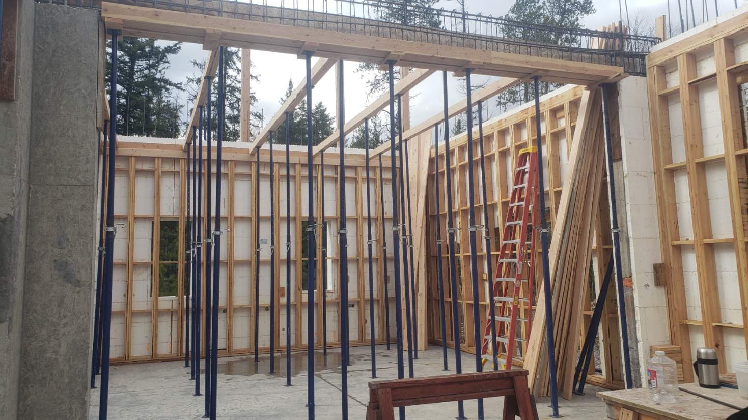
The photos from site, taken a few months later, show the system as drawn: adjustable steel props under timber beams, with the beam carried on its own row of props.
Check the props, not just the lumber
- Extension. An adjustable steel prop loses capacity as it is extended. Take the allowable load from the manufacturer's table for the actual extension, not the shortest one.
- Plumb and braced. A prop that leans carries less, and an unbraced row can buckle as a whole.
- What is underneath. Props need firm ground or a slab that can take the load, on sole plates where needed.
- Floors below. On multi-storey work, the floors below may need backpropping until the new slab can carry itself.
Timber or a system?
The logic is the same; only the parts change.
For a two-storey villa in Turks and Caicos, the suspended slabs and beams are formed in 1-inch wood panels on two layers of 2×4 lumber over shores, with bridge brackets and bracing at the beam sides. Each slab level is poured in two parts, with its lumber and panel quantities listed per pour.
For a multi-storey house in Aruba, the slabs are formed in the Doka system: H20 timber beams on Eurex 30 floor props with lowering and supporting heads. The drawings list every Doka part per slab area: 80 H20 beams and 76 Eurex props for one of them.
Systems are faster to set and strip, and come with the manufacturer's load tables. Timber is cheaper to buy and can be cut to any shape. The layout drawing is the same either way.
What a slab shoring drawing should show
- Each layer (deck, joists, beams, props) on its own plan, or clearly separated
- The spacing of joists, beams and props, dimensioned to the grid
- Beam bottoms and beam sides, with their own props
- The prop type, its extension range and its head
- Bracing, sole plates, and what the props stand on
- The pour sequence and construction joints, if the slab is poured in parts
- The stripping and backpropping sequence
- Quantities per pour
A note on engineering
Loads, prop capacities and bracing must follow ACI 347R or your local code, and the manufacturer's data for the props and system you use. If your contract or jurisdiction requires shoring drawings sealed by a licensed engineer, tell us when you ask for a quote.
#Formwork, #FormworkDesign, #SlabFormwork, #Shoring, #ShopDrawings, #ConcreteConstruction


